Modern near-Earth space is a highly dynamic and increasingly crowded environment. Thousands of active payloads, retired spacecraft, and fragmented pieces of space debris circle our planet at extreme velocities. Tracking these objects in real time requires a sophisticated blend of astrodynamics, computational propagation models, and reliable sensory data networks. A live satellite tracker acts as a bridge between abstract mathematical equations and tangible physical assets orbiting overhead, providing researchers, radio amateurs, and enthusiasts with precise spatial coordinates. Understanding how these tracking systems operate requires a deep dive into the physics of orbital mechanics and the administrative systems that keep cataloged objects organized.
Contents
The Architecture of Orbital Telemetry and Data Sourcing
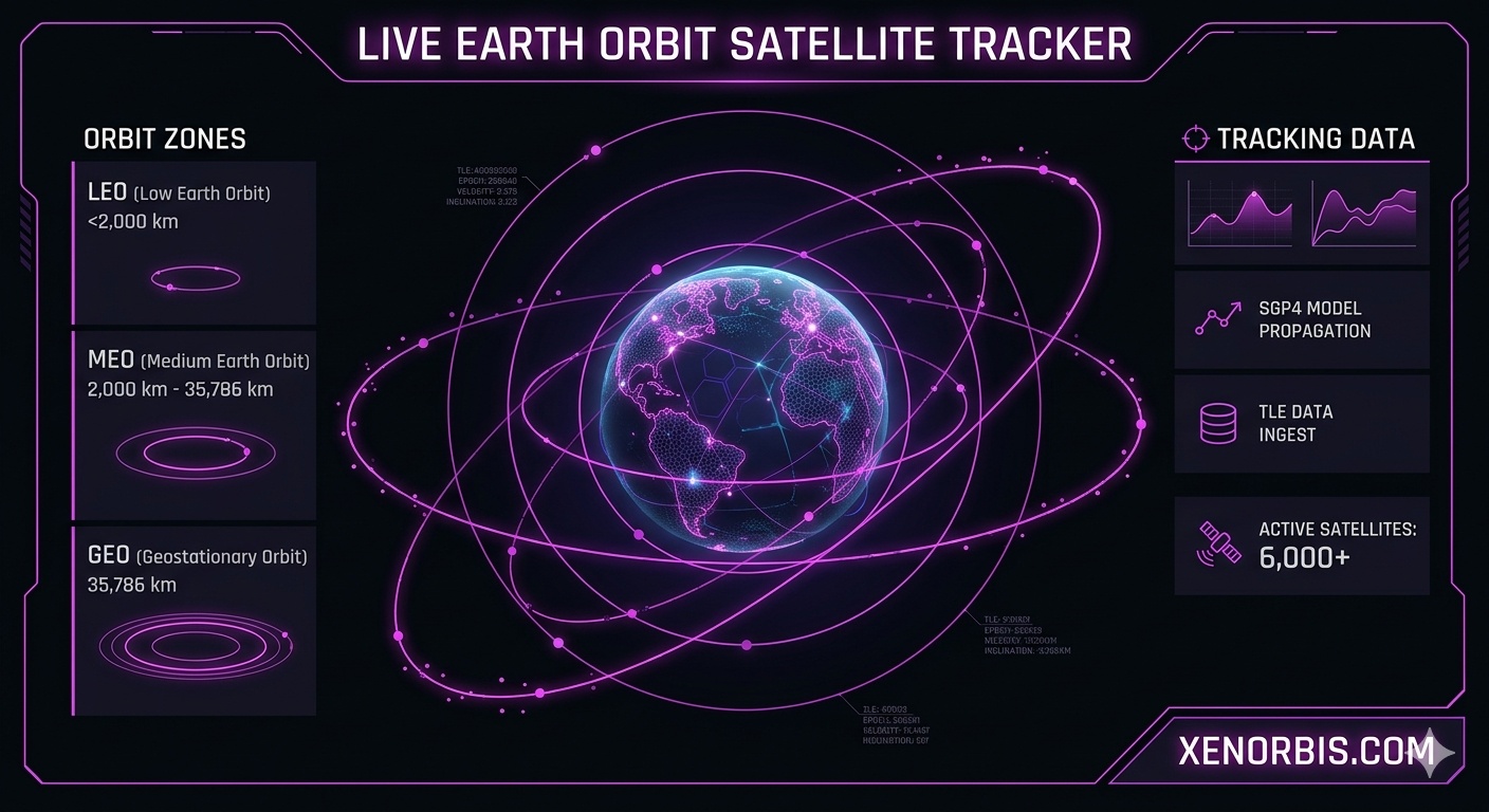
At the core of any digital tracking application lies the necessity to predict where a spacecraft will be at any given fraction of a second. Space tracking stations utilize various data inputs, but the foundational source of civil orbital data remains the Two-Line Element set, universally known as a TLE. Generated primarily by the United States Space Command via radar networks and optical tracking systems, a TLE is a specific data format containing a snapshot of a satellite’s orbital elements at a precise moment in time, referred to as the epoch.
Because Earth is not a perfect sphere and possesses an uneven gravitational field, satellites do not follow flawless, immutable paths. Atmospheric drag in lower regions, solar radiation pressure, and the gravitational pull of the Moon and Sun constantly warp these trajectories. To account for these perturbations, tracking software utilizes analytical propagation algorithms. The standard models for civil applications are SGP4, meaning Simplified General Perturbations 4, for near-Earth objects and SDP4 for deep-space or synchronous payloads. These algorithms ingest TLE data and execute complex mathematical transformations to output accurate inertial position vectors. Without continuous updates to these element sets, prediction models diverge from reality within days, making real-time tracking software essential for maintaining precise orbital situational awareness.
Fundamental Mathematical Formulations in Astrodynamics
To calculate the precise behavior of a satellite, engineers rely on classic laws of physics adapted for orbital environments. The velocity of a spacecraft in a perfectly circular orbit is determined by the balance between centripetal acceleration and gravitational attraction. This relationship is expressed through the fundamental velocity equation:
v = √[μ / r]
In this formulation, v represents the orbital velocity vector, μ is the standard gravitational parameter of Earth, and r is the distance from the center of the planet to the spacecraft. The Earth’s gravitational parameter itself is derived from the product of the universal gravitational constant and the mass of the planet:
μ = G × M
Where G equals 6.6743 × 10⁻¹¹ m3 kg-1 s-2 and M stands for approximately 5.972 × 1024 kg. This results in a constant μ value of roughly 3.986 × 10¹⁴ m3 s-2. For an object orbiting at a typical altitude of 400 kilometers above the surface, the radius r must include the Earth’s average radius of 6371 kilometers, yielding a total value of 6771 kilometers. Plugging these numbers into the formula reveals an orbital velocity of approximately 7.67 kilometers per second.
Another vital metric is the orbital period, which defines the exact time required for a satellite to complete one full revolution around the globe. This calculation stems directly from Kepler’s Third Law and is structured as follows:
T = 2 × π × √[a3 / μ]
Here, T represents the orbital period in seconds, while a denotes the semi-major axis of the orbit. For a circular trajectory, the semi-major axis is identical to the orbital radius r. Utilizing the same 400-kilometer altitude example, this equation yields a period of roughly 5550 seconds, which translates to approximately 92.5 minutes per orbit.
When ground stations attempt to establish communication with a fast-moving spacecraft, they must compensate for the compression or expansion of radio waves caused by relative motion. This phenomenon, known as the Doppler shift, modifies the received signal frequency according to the following equation:
fr = ft × [1 – vr / c]
In this radio communication formula, fr is the observed frequency at the ground station, ft is the original transmitted frequency from the satellite payload, vr is the relative radial velocity between the observer and the spacecraft, and c represents the constant speed of light in a vacuum, which is approximately 299792458 meters per second. A positive radial velocity indicates the satellite is moving away from the station, causing a drop in frequency, while a negative value signifies approach, causing a frequency spike.
Spatial Segmentation of Earth Orbits
Satellites are distributed across several distinct regions of space based on their mission profiles, sensor requirements, and communication coverage targets. These regions are characterized by their altitude boundaries and the specific physics governing their environments.
| Orbit Classification | Altitude Boundaries | Average Orbital Speed | Primary Strategic Purpose |
|---|---|---|---|
| Low Earth Orbit [LEO] | 160 to 2000 kilometers | 7.3 to 7.8 km/s | High-resolution imaging, global internet constellations, scientific research |
| Medium Earth Orbit [MEO] | 2000 to 35786 kilometers | 3.1 to 4.9 km/s | Global navigation satellite systems, regional communication, plasma research |
| Geostationary Orbit [GEO] | Exactly 35786 kilometers | 3.07 km/s | Continuous weather monitoring, television broadcasting, military warning |
| Highly Elliptical Orbit [HEO] | Variable; perigee low, apogee high | Variable; fastest at perigee | High-latitude communications, polar meteorology, magnetosphere studies |
- Low Earth Orbit contains the vast majority of active tracking targets due to the low energy required to launch payloads into this zone. It is home to the International Space Station and massive commercial communication constellations. However, the presence of residual atmospheric molecules causes persistent orbital decay, meaning satellites in lower LEO brackets must regularly fire thrusters to maintain altitude or face destructive re-entry.
- Medium Earth Orbit is optimized for navigation architectures like GPS, GLONASS, and Galileo. By placing constellations at altitudes around 20000 kilometers, orbital periods extend to roughly twelve hours, allowing a relatively small number of satellites to provide continuous global geometric coverage.
- Geostationary Orbit offers the unique advantage of an orbital period that matches the rotational period of the Earth exactly, which is 23 hours, 56 minutes, and 4 seconds. Consequently, a satellite placed in GEO above the equator appears completely stationary to a ground observer, eliminating the need for complex motorized tracking dishes.
Decoding the Keplerian Element Set
To fully map an orbital trajectory in three-dimensional space without complex vector mathematics at every step, astrodynamists utilize a set of six parameters known as the Keplerian elements. These numbers define the shape of the orbit, its orientation relative to the planet, and the location of the satellite within that specific path.
| Orbital Parameter | Standard Symbol | Angular or Linear Unit | Tracking Significance |
|---|---|---|---|
| Semi-Major Axis | a | Kilometers or meters | Defines the size of the orbit and dictates the total orbital period |
| Eccentricity | e | Dimensionless; 0 to 1 | Specifies the elongation of the ellipse, where 0 is perfectly circular |
| Inclination | i | Degrees; 0 to 180 | Measures the tilt of the orbital plane relative to the equator |
| Right Ascension of Ascending Node | Ω | Degrees; 0 to 360 | Defines the horizontal orientation of the orbital plane in space |
| Argument of Perigee | ω | Degrees; 0 to 360 | Determines where the lowest point of the orbit faces within its plane |
| Mean Anomaly at Epoch | M0 | Degrees; 0 to 360 | Pinpoints the position of the satellite along its path at the epoch time |
Using these six numbers, a tracking engine can construct a precise coordinate frame. The semi-major axis and eccentricity dictate the geometry of the trajectory loop. Inclination establishes how far north and south the satellite will travel during its orbit; for instance, a satellite with an inclination of 51.6 degrees will never pass directly over the polar regions, but it will routinely sweep across mid-latitude populated zones.

The remaining angles orient the orbit in three-dimensional space. The Right Ascension of the Ascending Node acts as a celestial longitude marker, pinning the spot where the satellite crosses the equator moving from south to north. The Argument of Perigee rotates the elliptical shape within its own plane, ensuring the tracking system knows exactly where the satellite reaches its maximum speed. Finally, Mean Anomaly acts as a cosmic clock, allowing the software to step forward in time from the epoch and calculate the exact current position of the vehicle.
The Critical Imperative of Real-Time Tracking Assets
Operational live tracking software serves vastly deeper purposes than simple visual amusement. As the commercialization of space accelerates, orbital tracking becomes a critical component of international infrastructure preservation, asset protection, and scientific validation. The primary drivers behind the continuous advancement of tracking tech span several distinct domains of engineering and space safety.
- Space Debris Mitigation and Collision Avoidance: Decades of orbital activity have left hundreds of thousands of untracked fragments spinning around Earth. Tracking applications cross-reference vectors to predict close approaches, enabling operators to execute evasive maneuvers before a catastrophic impact occurs.
- Radio Frequency Coordination and Signal Acquisition: Motorized ground stations must know precisely where to point directional high-gain antennas to pull telemetry from passing satellites. Real-time updates prevent signal loss and allow automated systems to pre-calculate Doppler compensation curves.
- Satellite Constellation Management: Managing networks consisting of thousands of nodes requires precise spatial distribution metrics. Trackers verify that individual units are maintaining their correct slots within the orbital mesh architecture.
- Space Situational Awareness for Launch Windows: Rocket operators utilize live tracking catalogs to design launch trajectories that safely slice through operational orbital shells without risking a collision during ascent.
As the concept of the Kessler Syndrome looms—a theoretical scenario where a single major collision triggers a runaway chain reaction of debris creation—high-fidelity live tracking stands as the frontline defense against losing access to near-Earth space entirely.
Global NavigationL-band; L1, L2, L5 frequencies12 to 15 yearsUltra-stable rubidium and cesium atomic clocks, signal generators
| Spacecraft Operational Type | Standard Radio Band | Average Lifespan | Core Instrument Payload |
|---|---|---|---|
| Earth Observation | X-band and Ku-band | 5 to 7 years | Multispectral optical imagers, Synthetic Aperture Radar, altimeters |
| Telecommunications | Ka-band, Ku-band, C-band | 10 to 15 years | High-throughput transponders, phased array steerable antennas |
| Scientific Research | S-band and UHF | 2 to 5 years | Magnetometers, particle detectors, cosmic ray spectrometers |
Ground Station Kinematics and Local Coordinate Systems
While tracking algorithms compute positions using an inertial coordinate system centered on the Earth, a human observer or ground antenna requires a topocentric horizon coordinate frame. This system translates the global position vector into terms relevant to a specific point on the surface: Azimuth, Elevation, and Range.
🛰 Azimuth describes the horizontal angle of the satellite measured clockwise from true north. An azimuth of 90 degrees indicates the target is due east, while 180 degrees indicates due south. Elevation defines the vertical angle of the spacecraft above the observer’s local horizon plane. An elevation of 0 degrees means the satellite is sitting exactly on the horizon line, while 90 degrees indicates the object is at the zenith, directly overhead.
Range measures the linear distance from the observer’s instrument to the satellite in kilometers. Due to the curvature of the Earth, a satellite at a low elevation angle must transmit its signals through a much thicker layer of the atmosphere than a satellite at zenith. This atmospheric penetration distance introduces signal attenuation and ionospheric delay, factors that modern tracking stations must calculate in real time during high-speed data passes. Live tracking platforms seamlessly execute these coordinate transformations hundreds of times per second, converting raw celestial vectors into intuitive, real-time pointing data for automated tracking mounts.
Essential Technical Literature and Reference Textbooks
For those seeking to expand their understanding of the mathematics, programming paradigms, and physical laws underpinning orbital tracking software, several foundational works stand out as industry standards.
- Fundamentals of Astrodynamics — Authored by Roger R. Bate, Donald D. Mueller, and Jerry E. White. This classic text offers an accessible, highly mathematical introduction to orbital mechanics, Keplerian geometry, and trajectory determination.
- Orbital Mechanics for Engineering Students — Written by Howard D. Curtis. An exceptional reference for modern engineering applications, detailing computer-aided orbital design, relative motion mechanics, and satellite attitude dynamics.
- Spacecraft Attitude Determination and Control — Compiled by James R. Wertz. This comprehensive handbook focuses heavily on the engineering principles required to maintain a satellite’s orientation, sensor pointing accuracy, and hardware alignment in orbit.
- Satellite Technology: Principles and Applications — Authored by Anil K. Maini and Varsha Agrawal. A magnificent guide covering the operational systems of modern spacecraft, including communication links, thermal regulation, and telemetry tracking architectures.

Julian D. Thorne — Celestial Mechanics Developer
Researcher and 3D engine developer focused on interactive stellar systems. Julian bridges the gap between theoretical physics and real-time browser-based cosmos exploration.


